What Is a Battery Charger With a Quick Disconnect Connector?
A battery charger with quick disconnect connector combines a battery charging power unit with a connector designed to make repeated charger-to-battery connection and disconnection more practical.
The concept is particularly useful in industrial applications where equipment may need to be charged frequently or where the charger and battery are not permanently connected.
Typical applications can include:
- Material handling equipment
- Logistics equipment
- Battery-powered carts
- Industrial mobile equipment
- Service equipment
- Warehouse vehicles
- Replaceable battery systems
- OEM battery platforms
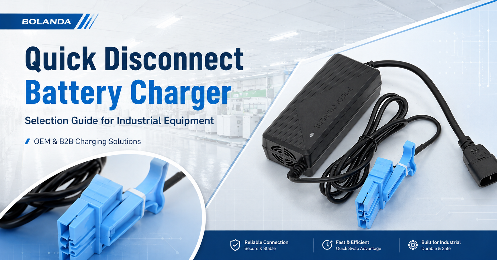
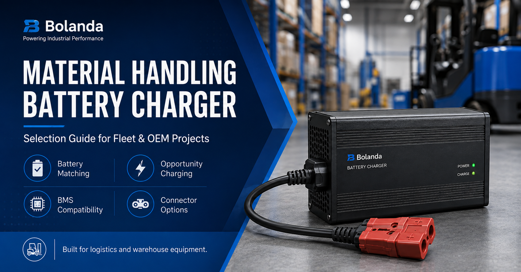
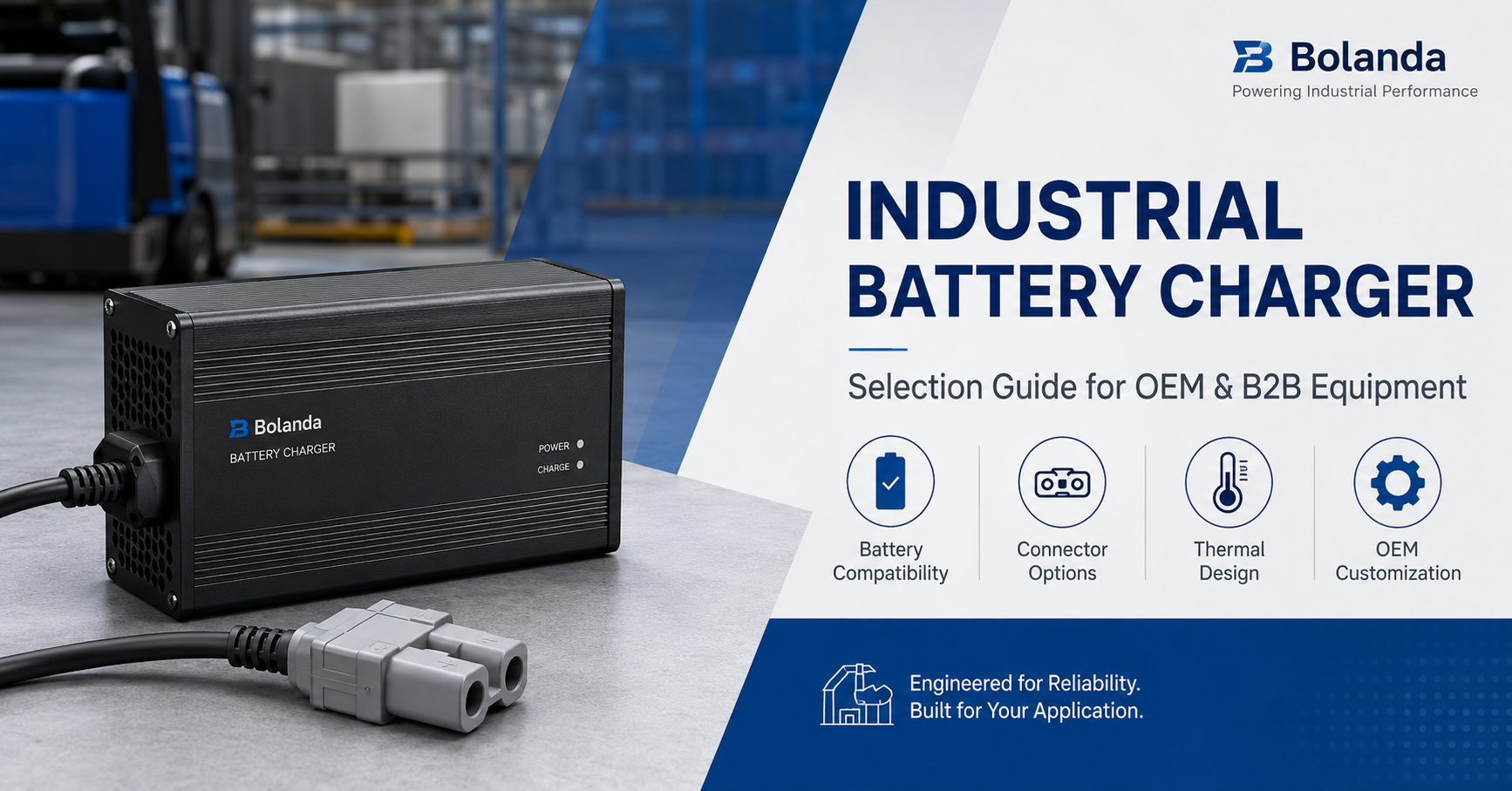
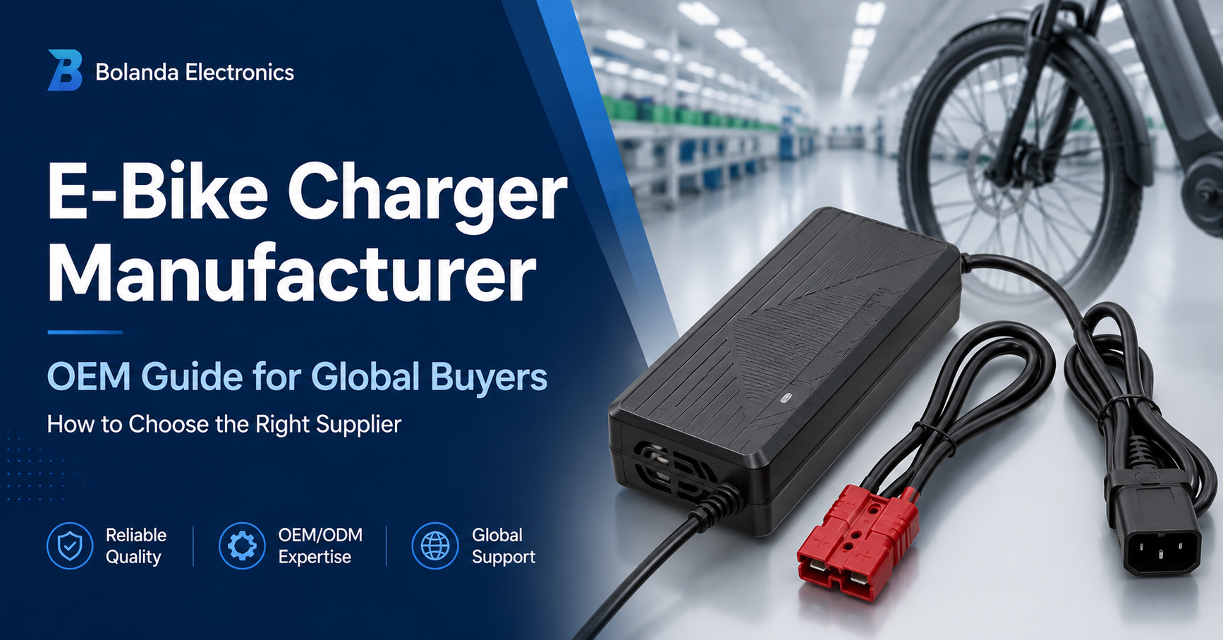
Bolanda's current public product center includes compact industrial battery charger configurations with red and blue two-pole quick disconnect connectors, as well as a gray two-pole connector version.
The connector, however, should be treated as part of the complete charging system rather than simply as a plug attached to the cable.
Why Use a Quick Disconnect Connector on a Battery Charger?
The primary purpose of a quick disconnect interface is to make repeated electrical connection easier than a permanent or tool-assisted termination.
In industrial applications, this can support:
- Faster charger connection
- Faster disconnection
- Repeated battery changes
- Charger sharing
- Fleet charging
- Service and maintenance
- Battery replacement
TE Connectivity describes quick-disconnect power-connector designs as alternatives to traditional terminal-lug connections, with keyed locking interfaces intended to simplify connection and servicing.
This does not mean every quick disconnect connector is suitable for every charger.
Connector selection still depends on electrical, mechanical, environmental, and battery-system requirements.
Connector Shape Alone Does Not Confirm Compatibility
One of the most important purchasing rules is:
A connector that physically fits is not automatically electrically compatible.
Two battery connectors can look almost identical but differ in:
- Positive and negative terminal arrangement
- Current rating
- Contact size
- Cable size
- Mechanical keying
- Auxiliary contacts
- Material
- Environmental protection
The buyer should therefore verify the exact connector specification instead of purchasing only from a photo.
For replacement charger projects, a physical sample or drawing is especially valuable.
Do Not Choose a Battery Connector by Color Alone
Color can be useful for identification, but it should not be treated as the electrical specification.
Anderson Power Products, for example, uses color-coded and mechanically keyed housings within its SB connector family to help distinguish interfaces and reduce cross-mating risk. Its documentation specifically explains that the housing colors and keys are used as identifiers between configurations.
The important sourcing lesson is not that every colored connector follows the Anderson system.
It is that connector color should be verified together with the actual connector family, keying, contacts, polarity, cable, and electrical rating.
Bolanda currently displays red, blue, and gray two-pole industrial charger connector configurations, but the final interface for an OEM project should be confirmed from the exact product specification.
What Does a Two-Pole Charger Connector Do?
A basic two-pole battery charging connector typically provides two main power conductors:
- Positive
- Negative
This can be sufficient for battery systems where charging control is handled without additional connector signals.
However, some battery systems need more than two conductors.
Additional contacts may be required for:
- Battery temperature
- Charge enable
- Battery identification
- CAN communication
- Interlock
- Status signals
Anderson's higher-function battery connector families, for example, can combine primary power contacts with auxiliary contacts for signaling and communication.
Therefore, buyers should determine whether a simple two-pole interface is actually appropriate for their battery system.
Start With the Battery Before Selecting the Connector
The connector should not be selected independently of the battery and charger.
Before choosing a quick disconnect interface, define the complete battery specification.
| Battery Requirement | Why It Matters |
|---|---|
| Battery chemistry | Determines charging profile |
| Nominal voltage | Identifies the system |
| Maximum charging voltage | Defines charger output requirement |
| Battery capacity | Helps determine charging current |
| Maximum charge current | Influences connector and cable sizing |
| BMS | May require additional signals |
| Charging interface | Determines connector configuration |
| Application | Influences durability requirements |
| Environment | Can affect connector material and protection needs |
The battery determines not only the charger parameters but also the electrical demands placed on the connector.
How to Select Connector Current Rating
Connector current capability is one of the most important parameters in an industrial charging system.
Charging current passes through:
- Charger PCB
- Internal wiring
- Output cable
- Connector contacts
- Battery wiring
- Battery protection system
If the connector is undersized, electrical resistance can create additional voltage drop and heat.
Anderson Power's connector product families demonstrate how widely connector current capability can vary: its Powerpole family spans different housing and wire sizes, while its SBS products provide different current levels depending on connector configuration.
These ratings are examples from those connector families, not specifications for Bolanda chargers.
For an OEM project, the actual connector should be selected according to the required charging current and its own verified manufacturer rating.
Current Rating Should Include the Entire Cable Assembly
Do not evaluate the connector by itself.
The complete output assembly includes:
charger → cable → contact termination → connector → battery
The current capability can be limited by any part of this path.
A useful OEM review should therefore consider:
- Connector contacts
- Cable conductor size
- Crimp or termination method
- Cable length
- Charger current
- Ambient temperature
- Duty cycle
The strongest connector in the system cannot compensate for an undersized cable.
Why Contact Resistance Matters
Every electrical connection has some resistance.
In a high-current charging path, resistance can contribute to:
- Voltage drop
- Connector heating
- Energy loss
- Local thermal stress
Connector suppliers therefore often use contact materials and plating intended to maintain low electrical resistance and durability.
Anderson states that silver-plated contacts are used in its SB connector series to reduce electrical resistance while supporting durability.
For B2B buyers, the practical point is to select verified connector components and monitor connector temperature during charger validation.
Cable Size Must Match Charging Current
A charger with the correct connector can still be poorly designed if the output cable is not appropriate.
Cable selection should consider:
- Charging current
- Cable length
- Conductor material
- Temperature rating
- Flexibility
- Installation environment
- Repeated handling
Longer cables can also contribute to additional voltage drop.
For industrial applications, cable design may need to balance electrical performance with flexibility and durability.
Bolanda currently lists Connector & Cable as one of the OEM/ODM project configuration areas it can review.
Cable Strain Relief Is Important for Repeated Use
Industrial charger cables can experience frequent movement.
Common stresses include:
- Pulling
- Twisting
- Bending
- Dragging
- Repeated connector insertion
- Incorrect disconnection by pulling the cable
The cable entry and connector termination should therefore have suitable strain relief.
Without it, repeated mechanical force can be transferred to:
- Conductors
- Crimp terminals
- Solder joints
- Charger internal wiring
For fleet and warehouse applications, mechanical cable durability can be just as important as electrical performance.
Mechanical Keying Helps Prevent Incorrect Connection
Mechanical keying can prevent incompatible connectors from mating.
This is useful where:
- Multiple battery voltages are used
- Several charger types are installed nearby
- Different equipment shares one charging area
- Operators connect chargers frequently
Anderson's SB series uses keyed housings specifically to prevent cross-mating between incompatible configurations.
An OEM charger project can use the same general design principle even when another connector family is selected:
Make incompatible battery systems physically difficult or impossible to connect incorrectly.
Mating-Cycle Durability Matters in Industrial Applications
A connector installed once has different requirements from one connected several times every day.
Consider a charger used:
- 3 times per day
- 300 operating days per year
- For several years
The connector may experience thousands of mating cycles over the life of the equipment.
Some industrial battery connector systems are specifically designed around high mating-cycle durability. Anderson, for example, lists up to 10,000 mating cycles for certain SBE/SBO/SBX connector configurations.
Again, that is a specification of those connector products rather than Bolanda's general connector range.
For a charger project, ask the selected connector manufacturer for its actual rated mechanical life.
Quick Disconnect Does Not Automatically Mean Safe to Disconnect Under Load
This is an important distinction.
A connector may be designed for convenient physical disconnection without necessarily being intended to interrupt the full charging current while energized.
Some specialized connector systems are explicitly rated for current interruption, while others are not. Anderson's Saf-D-Grid documentation, for example, specifically identifies configurations rated for current interruption.
For an industrial charger project, ask:
- Should the charger be switched off before disconnection?
- Does charging current stop before the connector is separated?
- Is an interlock required?
- Is the selected connector rated for current interruption?
Do not assume “quick disconnect” means “disconnect safely under full electrical load.”
BMS Requirements Can Change Connector Design
Lithium battery systems frequently use a battery management system.
Depending on the design, charging may require more than positive and negative power.
The BMS may need:
- Temperature signal
- Charge-enable line
- Battery identification
- Communication
- Interlock
If those functions need to pass between the charger and battery, a simple two-pole connector may not be enough.
This should be identified during the first engineering review rather than after the connector is selected.
Quick Disconnect Connector Selection Checklist
| Selection Area | Question |
|---|---|
| Connector type | What exact connector family is required? |
| Number of poles | Two power contacts or auxiliary signals? |
| Current | What charging current must it support? |
| Voltage | What system voltage is used? |
| Polarity | Which terminals are positive and negative? |
| Keying | Can incompatible systems cross-mate? |
| Cable size | What conductor size is required? |
| Mating cycles | How frequently is it connected? |
| Environment | Indoor, warehouse or harsh environment? |
| Strain relief | How is cable stress controlled? |
| Interlock | Can charging stop before disconnect? |
| BMS | Are signal contacts required? |
This checklist can prevent many common connector-selection errors.
Environmental Conditions Should Be Considered
Industrial battery chargers may be used in:
- Warehouses
- Workshops
- Factories
- Service areas
- Agricultural equipment environments
- Material handling facilities
Connector design may therefore need to account for:
- Dust
- Moisture
- Temperature
- Vibration
- Chemical exposure
- Repeated handling
Dedicated industrial battery connector systems can include sealing and environmental protection features. Anderson's Industrial Battery Connector, for example, is designed for material-handling and ground-support environments and includes an IP68 sealing option.
This does not mean every charger requires IP68 protection.
Environmental protection should match the actual application.
Connector Location Affects User Experience
Connector engineering is also a usability question.
Consider:
- Can the operator reach the connector easily?
- Does the cable have enough length?
- Can the connector be inserted in the wrong orientation?
- Does the connector lie on the floor?
- Can equipment run over the cable?
- Is there a convenient storage position?
- Can the user disconnect it without pulling the cable?
For fleet systems, small usability problems can become significant when repeated hundreds of times.
Quick Disconnect Connector vs Fixed Connection
| Factor | Quick Disconnect | Fixed Connection |
|---|---|---|
| Battery replacement | Easier | More difficult |
| Charger sharing | Easier | Limited |
| Serviceability | Strong | More involved |
| Repeated connection | Designed for this use when appropriately specified | Not primary purpose |
| Mechanical wear | Must be considered | Lower mating wear |
| Connector cost | Additional component | Potentially lower |
| User convenience | High | Lower |
| Best use | Fleets, removable batteries, industrial charging | Permanent installations |
Neither approach is automatically better.
The decision depends on how the equipment is operated and serviced.
When Is a Quick Disconnect Battery Charger Most Useful?
This charger format can be particularly useful for projects involving:
Material Handling Equipment
Forklifts, carts and warehouse equipment can require frequent charging or battery changes.
Logistics Equipment
Chargers may be shared across equipment in designated charging areas.
Replaceable Battery Packs
Quick disconnect interfaces can make battery swaps easier.
Fleet Equipment
Repeated daily connection makes connector durability important.
Service Equipment
Maintenance teams may need convenient battery access.
Bolanda specifically identifies logistics lithium equipment chargers among its core electronic power product categories.
What Should Be Tested During Sample Approval?
A charger sample should be tested as a complete charger and cable assembly.
Electrical Verification
Check:
- Output voltage
- Charging current
- Charging profile
- Charge termination
Connector Verification
Check:
- Polarity
- Pin arrangement
- Contact engagement
- Current capability
- Mechanical fit
Thermal Verification
During representative charging cycles, evaluate:
- Connector temperature
- Cable temperature
- Charger housing temperature
Unexpected connector heating can indicate issues involving contact resistance, termination, current, or cable selection.
Mechanical Verification
Repeat connection and disconnection.
Check:
- Insertion force
- Removal force
- Connector retention
- Cable strain relief
- Keying
- Housing durability
Battery Compatibility
Use the actual battery whenever practical.
The connector can be correct while the charging parameters remain incompatible.
OEM Customization for Quick Disconnect Charger Projects
Bolanda's current public OEM/ODM framework provides several relevant project-review areas.
Connector and Cable
This is directly relevant to quick disconnect charger projects.
The required connector and cable configuration can be reviewed against the selected charger and battery application.
Input and Output
Electrical parameters should match the battery and application.
Charging Parameters
Charging requirements can be evaluated according to the confirmed battery system.
Housing and Label
Product identification and branding requirements can be reviewed.
Plug Standard
AC-side configuration can be reviewed for the target market.
Packaging
OEM packaging can be defined around the confirmed project.
Bolanda currently displays compact industrial charger versions using red, gray, and blue two-pole connectors, giving buyers several existing product configurations as starting points for project evaluation.
Common Procurement Mistakes
Selecting from connector color only
Risk: Similar-looking connectors may have different keying or specifications.
Better approach: Confirm exact connector type and drawing.
Ignoring polarity
Risk: Incorrect polarity can create serious equipment or battery problems.
Better approach: Define pinout in the approved specification.
Choosing a connector with insufficient current capability
Risk: Excessive contact heating and voltage drop.
Better approach: Match the connector to actual charging current and operating conditions.
Ignoring cable size
Risk: The connector may be adequate while the cable is undersized.
Better approach: Validate the complete cable assembly.
Disconnecting under load without confirmation
Risk: The connector may not be designed to interrupt charging current.
Better approach: Define the correct disconnect procedure or interlock strategy.
Assuming the BMS only needs two wires
Risk: Some battery systems require signal or communication contacts.
Better approach: Confirm BMS interface requirements before selecting the connector.
What Information Should You Send in the RFQ?
| RFQ Item | Information to Provide |
|---|---|
| Application | Equipment or battery system |
| Battery chemistry | Exact chemistry |
| Nominal voltage | Battery system voltage |
| Charging voltage | Required final charging voltage |
| Charge current | Target and maximum |
| Battery capacity | Ah or Wh |
| BMS | Interface requirements |
| Connector | Part number, photo, drawing or sample |
| Polarity | Positive and negative terminals |
| Cable | Length and conductor requirement |
| Mating frequency | Estimated connection cycles |
| Environment | Temperature, dust, moisture |
| Input | AC requirements |
| Plug | Target-market requirement |
| Quantity | Prototype and production forecast |
Bolanda's current quotation guidance asks buyers to provide product type, input and output requirements, battery information, connector, estimated quantity, and target market.
For this type of project, providing an actual connector sample can make the evaluation substantially more reliable.
Frequently Asked Questions About Quick Disconnect Battery Chargers
What is a quick disconnect battery charger?
It is a battery charger equipped with a connector intended to make charger-to-battery connection and disconnection convenient. The exact connector still needs to match the battery's voltage, current, polarity, cable, and interface requirements.
Are red and blue battery connectors interchangeable?
Not automatically. In some connector families, colors can correspond to different keyed configurations. The exact connector part number and mechanical keying should be confirmed rather than relying on color. Anderson's SB family is one example where colored keyed housings are used to prevent cross-mating.
What does a two-pole battery connector mean?
A basic two-pole connector provides two main electrical contacts, normally positive and negative power. Battery systems requiring communication or sensing may need additional contacts.
How do I select connector current rating?
Start with the maximum charger current and verify the selected connector, contacts, cable size, termination, ambient conditions, and duty cycle against their actual ratings.
Can a quick disconnect connector be disconnected while charging?
Not necessarily. Some connectors are specifically rated for current interruption, but many should not be assumed to have that capability. Confirm the connector specification and charger operating procedure.
Why does the connector become warm during charging?
Potential causes can include contact resistance, high current, poor termination, undersized cable, damaged contacts, or an unsuitable connector. The cause should be investigated rather than assuming heating is normal.
Can Bolanda provide different connector colors?
Bolanda currently displays compact industrial charger products with red, blue, and gray two-pole connector configurations. Exact availability and compatibility should be confirmed for the selected product.
Can the connector and cable be customized?
Bolanda lists connector and cable requirements within its current OEM/ODM project-review framework. Final feasibility depends on the selected charger, electrical requirements, connector, and order scope.
Can charging voltage and current also be customized?
Bolanda currently lists input/output and charging parameters as project configuration areas, but the final specification must be confirmed through technical review.
What should I send before requesting a quotation?
Provide battery chemistry, voltage, current, capacity, BMS information, connector part number or sample, cable requirements, application, environment, target market, and estimated quantity.